Pulse width modulation (PWM) is a technique of controlling the amount of power delivered to an electronic load using an on-off digital signal. Pulse Width Modulation (PWM) has a wide range of applications such as speed control in DC motor, sine wave generation, generating analog voltages and so on. Simply, PWM signals are ON or OFF signals whose ON period can be controlled based on our requirements. Duty cycle can be defined as the portion of the time period in which the device or system is operating. Or it can be defined as the ratio of the ON time to the total period of the pulse. So we can control the duty cycle to meet our requirements.

TON = ON time of the pulse
T = Total time period of the pulse
Thus by controlling TON, we can control the speed of a DC motor or we can control a servo motor or else we can control the brightness of an LED.
The below given figure represent a PWM signal of different duty cycles to control the brightness of an LED.
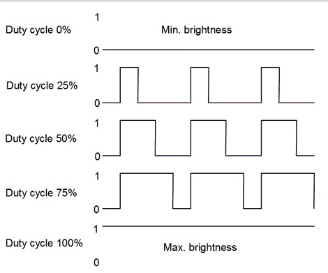
Fig 1: PWM SIGNAL OF DIFFERENT DUTY CYCLES
The brightness of LED is increased when the duty cycle increases from 0 to 100. PWM can be generated by using CCP modules available with most of the PIC microcontrollers. But there are certain conditions which lead to a situation in which we cannot use the available PWM module. Those conditions are mentioned below.
1. In some controllers, there is no inbuilt PWM module.
2. In some applications, the available PWM module is not sufficient to serve our need.
In these conditions, we can use a PWM wave which can be generated by using software. Then, the next task is, how can we generate the PWM wave by using the software? Is it possible? Yes Of course. PWM wave of required pulse width can be generated manually by using software. I will explain it with an example of controlling a servo motor by PIC16F877A microcontroller with a manually generated PWM wave. The concept behind this can be explained in just four steps given below.
1. First, we should generate a triangular wave (VTRI) of user defined frequency.
2. Then the major thing is that we must have a reference signal (VREF). The value of this reference signal can be changed according to the required time period.
3. The third step is simply comparing these two signals.
4. If the value of the triangular wave is greater than the reference signal, the output will be one. Otherwise zero.
ie, if VREF >VTRI, the output will be one.
if VREF <VTRI, the output will be zero.

Fig 2: PWM GENERATION
Fig. 2 represents PWM generation from a triangular (carrier signal) and a reference signal. Now you got a basic concept of PWM generation. So our next task is to apply this PWM to a servo motor. Before that, you should learn an overview of servo motor operation.
Servos consist of three wires. First one is for providing power supply which is 5V; second for providing ground and the last one is for providing control signal which is the supreme factor. Servos are controlled by sending pulses of variable pulse width. Control wire is used to send this pulse.
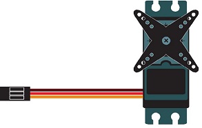
Fig 3: CREATIVE REPRESENTATION OF SERVO MOTOR
Creative representation of a servo motor (Fig 3) is provided just to recognise the functionality of three wires appears as three colours.
Brown: Ground
Red: Supply (5V)
Orange: PWM
Note: Colour may be varied according to the manufacturer. Just refer the data sheet of the particular servo motor to find out the exact pins.
Servo Motors rotates in certain angles, which is determined by the duration of a pulse that is applied to the control wire. This is exactly called Pulse Width Modulation (PWM). Every servo has a neutral position which is around 1.5 milliseconds and this will make the motor turn to 90º position. If we sent a pulse of less than 1.5ms, servo rotates to a position counterclockwise from the neutral point. If we sent a pulse of width more than 1.5ms, servo rotates to a position clockwise from the neutral point.
So simply, to rotate a servo to 0º we need a pulse width of 1ms and for 90º the pulse width is 1.5ms and for 180º the pulse width is 2ms.
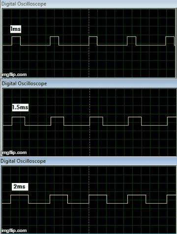
Fig 4: 1ms, 1.5ms, 2ms PULSEWIDTH FOR SERVO MOTOR
Fig.4 shows 1ms, 1.5ms and 2ms pulse width required for controlling servo. In the case of DC motors, we can reverse the power supply polarity to reverse the rotation. But in the case of Servo motor, reversing of power supply polarity does not reverse the rotation otherwise it may damage the control circuitry. I think you have got a basic idea of working of servo motor.
The simulation diagram is provided below. Just refer figures 5,6 and 7. Here the program will control a servo with the help of three external switches. That is whenever the switch S1 is ON, the servo should rotate 90º counter clockwise direction from the initial position and when the switch S2 is ON, the servo will rotates back to its original position. When the switch S3 is ON, the servo will rotate 90º clockwise direction. Thus a total of 180º rotation is possible by using the three pulses.
From fig.5, it is clear that the switch S1 is closed. We can see from the zoomed view of motor that the degree of rotation is provided as -90°. Fig.6 shows the closed condition of the switch S2. And whenever the switch S2 is closed, the motor will rotate clockwise direction from the previous position and it reaches the 0º position. Fig.7 shows the closed condition of the switch S3. When the switch S3 is closed, the motor will rotate clockwise direction from the 0º position and it reaches the +90º position.
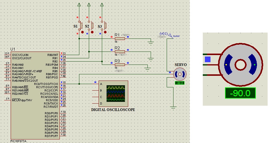
Fig 5: SIMULATION DIAGRAM OF PWM CONTROLLED SERVO IN PROTEUS WHEN SWITCH 1 IS CLOSED AND ZOOMED VEIW OF MOTOR

Fig 6: SIMULATION DIAGRAM OF PWM CONTROLLED SERVO IN PROTEUS WHEN SWITCH 2 IS CLOSED AND ZOOMED VEIW OF MOTOR
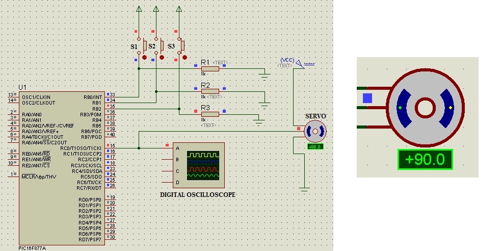
Fig7: SIMULATION DIAGRAM OF PWM CONTROLLED SERVO IN PROTEUS WHEN SWITCH 3 IS CLOSED AND ZOOMED VEIW OF MOTOR
Now the crucial fact is how to generate pulse width of 1ms, 1.5ms and 2ms by using software. The Mplab code regarding that is provided below.
#include <stdio.h>

#include <stdlib.h>

#define _XTAL_FREQ 16000000

// PIC16F877A Configuration Bit Settings

// 'C' source line config statements

#include <xc.h>

// #pragma config statements should precede project file includes.

// Use project enums instead of #define for ON and OFF.

// CONFIG

#pragma config FOSC = HS

#pragma config WDTE = OFF

#pragma config BOREN = ON

#pragma config LVP = OFF

#pragma config CPD = OFF

#pragma config WRT = OFF

#pragma config CP = OFF

void first_pulse();

void second_pulse();

void third_pulse();

int i;int ref1=65,ref2=100,ref3=135;

void main()

{

while(1)

    {

    TRISC=0x00;

    TRISB=0XFF;


        if(RB0==1)
        {
       first_pulse();
        }

       else if(RB1==1)
        {
       second_pulse();
        }

       else if(RB2==1)
       {
       third_pulse();
       }

    }

}


//FUCNTIONS FOR GENERATING PULSES


 void first_pulse() //for generating 1 millisecond pulse for 0°

    {

    for(i=0;i<300;i++)

    {

        if(ref1>i)

        {

            RC0=1;

        }

        else

        {

           RC0=0;

        }

    }

    for(i=300;i>=0;i--)

    {

        if(ref1>i)

        {

            RC0=1;

        }

        else

        {

            RC0=0;

        }

    }

    }


 void second_pulse()  //for generating 1.5 millisecond pulse for 90° rotation

    {

    for(i=0;i<300;i++)

    {

        if(ref2>i)

        {

            RC0=1;

        }

        else

        {

           RC0=0;

        }

    }


    for(i=300;i>=0;i--)

    {

        if(ref2>i)

        {

            RC0=1;

        }

        else

        {

            RC0=0;

        }


    }

    }

 void third_pulse()   //for generating 2 millisecond pulse for 180° rotation

    {

    for(i=0;i<300;i++)

    {

        if(ref3>i)

        {

            RC0=1;

        }

        else

        {

           RC0=0;

        }

    }


    for(i=300;i>=0;i--)

    {

        if(ref3>i)

        {

            RC0=1;

        }

        else

        {

            RC0=0;

        }


    }

    }
From the code, it is clear that PORTB is set as input port so that we can connect the external switches to this port. PORTC is set as output port so that the output servo is connected to PORTC. Then the next thing is, when the switch S1 is ON, a pulse of width 1ms is sent to the servo. When the switch S2 is ON, the pulse width is 1.5ms and when S3 is ON, pulse width is 2ms. Then the main factor is that, how can we generate the pulses of these specific width. That is the main concept in this tutorial.
To generate pulses of width 1ms, 1.5ms and 2ms, we need a triangular carrier signal and a reference signal that i mentioned before. Just refer fig.2. The count of the carrier wave (triangular wave )can be increased from zero to a maximum value which can be determined by the user. Also there is a reference signal whose value can be changed to get a pulse of desired pulse width. By modifying these two values we can generate a PWM of user defined frequency.
Here, in order to get a pulse of 1ms width, the count chosen is 300 and reference is set to be 65. For generating other pulses, count need not be modified. That means count is 300 constantly but the reference is modified. The reference values are 100 and 135 for generating pulse widths of 1.5ms and 2ms respectively.

Fig 8: DSO IMAGE OF PULSE WIDTH MODULATION OF PULSES 1MS,1.5MS AND 2MS FOR 0º TO 180º ROTATION OF SERVO
Fig.8 shows the DSO image of pulses 1ms,1.5ms and 2ms after the experimental verification of software PWM. Thus by applying pulses of 1ms, 1.5ms and 2ms we can control the servo in between 0° and 180º. More specifically, if the pulsewidth is 1ms the servo moves to 0º and if the pulsewidth is 1.5ms the servo moves to 90º and if the pulsewidth is 2ms the servo moves to 180º. This is how a simple conceptual servo motor works.
CONCLUSION
There are certain conditions in which we cannot use the inbuilt PWM module in several microcontrollers which I mentioned above. Or there are several microcontrollers which does not have an inbuilt PWM module. In those cases we can effectively use the above mentioned method of generating PWM of desired pulse width. This method is verified experimentally.
RELATED LINK